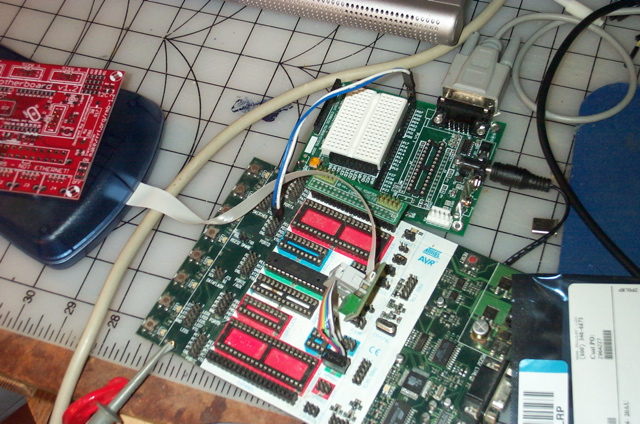
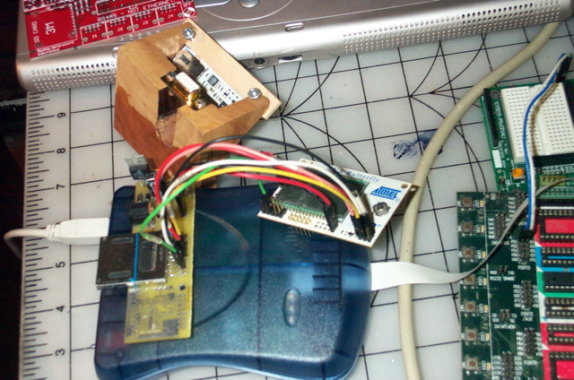
I mistyped the name Reprap in the firmware code. Happy accident, I now have a name for my Repstap/Mendle project. This fits in well with the ratsnest of wires on the SDK500 mega168 project lashup.
As I do not care for the bloat of Arduino, I am writing my own firmware in assembly. Much of this I borrowed from one of the MIDI compact flash projects. This way I can use my already small footprint FAT12/16/32 code.
SD uses a serial interface for comms, so much of the low level code for initializing the card and reading blocks needs to be re-written. Using an AVR freaks tutorial, for butterfly SD card connectivity is a good way to test the code.
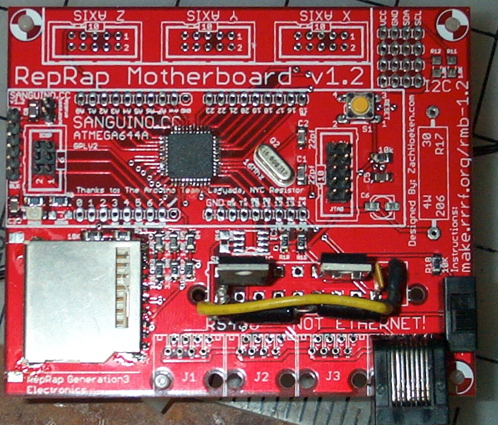
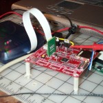
The supplier makerbot had a few remaining v1.2 controllers. This enabled me to not make a board from scratch. Since the SD card socket is in place I swiched over from the rats nest to the v1.2 board.
Weirdstuff, a surplus store in the silicon valley has some SD/MMC adapter cards for about 20 cents [USD] at this price I bought a couple dozen. With a heatgun and a thermocouple poping the connector off is a simple process. Provided one does not melt the plastic.
The makerbot/reprap “motherboard” controler v1.2 board has the pads and holes in the right place for these sockets. The shield on the cheap sockets is a bit smaller. Removing solder mask in these places allows for the MMC card to be attached to the board. Image 1 in the gallery below details where the solder mask was removed.
The board can be assembled either for use with an ATX supply or with a power brick. The 3.3 volt regulator I got from jameco has a different footprint than the recommended one. It is not a good idea to power a 3.3v regulator off of a 5v regulator. There is not enough headroom for the regulator to work. Looking at the ATX connector, it seemed the most efficient way to get power would be to tap the 12v line and add a standard 5v regulator. It worked out nicely to make a little bridge using the leads on the filter caps. This also gives some points where the bench supply can inject power.
The schematic indicates that the 12V is sent through the RJ45 connectors to the external controller boards. I like to recycle/reuse stuff, so I got some block of RJ45 from weirdstuff, which I de-soldered. Some of these I melted the tabs as I did not have any heatsheld. I mounted one of these extra connectors in case I want to inject power through this connector.
It is a bit annoying that the power switch is a relay trip. This means the AVR must always be powered. I still need to make some usb/rs232 boards for the FTDI chips I have about. These use an odd pitch footprint, which requires at least a breakout board. Ironically, I want to get this stuff working so I can drill the boards. I guess that is the rep part of the system. The rapid part is what my (C)NC is not.
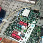
The gallery below shows some of the steps in bringing these boards online. I moved the ex at90s8515 code from the mega88/mega168 to the mega644. The mega168 to mega644 path is fairly straightforward. Some of the interrupt vectors are different. Mostly due to the second optional USART.
Now that I have a more stable less of a ratsnest prototyping setup, I expect to make more changes to the firmware. I am still considering using i2c to drive the steppers. The current layout consumes most of the pins. This makes adding multiple heads/axis a bit awkward. There are also a shortage of pins which can be used for button panels and readout displays. Of course these can be implemented through the serial coms, which would involve removing the existing code from the system.
-
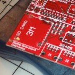
- Modifying the solder mask to take the cheap SD card connector

-
- STK ATmega168 lashup
-

- Butterfly SD/MMC lashup
-
- Overview of SD/MMC lashup

-

- Power conditioning modifications

-

- top view detail of power conditioning mods